The allure of flight, particularly with custom-built aerial platforms, captivates a significant segment of the engineering and hobbyist community. The accompanying video offers a compelling visual journey into the fabrication of a custom tricopter, showcasing the intricate assembly process through a hands-on demonstration. While the visual guide provides an excellent overview, truly mastering the art of building a custom drone, especially a distinctive multirotor like a tricopter, necessitates a deeper dive into the underlying principles, component selections, and calibration methodologies.
This comprehensive guide complements the visual narrative by elucidating the technical intricacies involved in designing, assembling, and tuning your own tricopter. We will explore the distinctive advantages of this three-rotor configuration, delve into the critical components that form its foundation, and outline a methodical approach to construction and flight readiness. Understanding these nuanced aspects is paramount for any enthusiast aiming to transcend off-the-shelf solutions and embark on the rewarding journey of creating a truly personalized aerial vehicle.
Understanding the Tricopter Advantage: A Distinctive Multirotor Architecture
Among the myriad multirotor configurations, the tricopter occupies a unique niche, primarily distinguished by its three-motor layout and, crucially, a mechanical yaw mechanism. Unlike quadcopters that achieve yaw through differential motor thrust, a tricopter typically employs a servo-controlled tilt mechanism on its rear motor. This fundamental difference confers several operational and aesthetic benefits that appeal to discerning builders.
Firstly, the servo-driven yaw provides an exceptionally direct and precise control over the yaw axis, often resulting in a more fluid and “locked-in” feel during maneuvers. Imagine if your drone could pivot with the surgical precision of a high-performance aircraft; this is the tactile advantage a well-tuned tricopter often presents. Furthermore, with only three motors, the power train can sometimes be simplified, potentially leading to marginal gains in efficiency or a reduction in component count, depending on the specific design objectives. This also means fewer Electronic Speed Controllers (ESCs) and motors to manage, which can slightly reduce complexity during initial wiring and troubleshooting phases.
Moreover, the aesthetic and aerodynamic profile of a tricopter is often favored by pilots who appreciate its less conventional appearance. The unique rear arm and tilting mechanism offer a distinctive silhouette that stands apart from the ubiquitous quadcopter. For those seeking to push the boundaries of custom drone design and flight dynamics, understanding the nuances of how a tricopter manages its flight envelope is the first step towards a successful build.
Deconstructing the Tricopter Yaw Mechanism
The hallmark of the tricopter’s design is its innovative approach to yaw control. Instead of relying solely on motor speed differentials, which can be less precise for three-rotor systems, the rear motor on a tricopter is mounted on a pivot. This pivot is actuated by a dedicated servo motor, which physically tilts the rear propeller to vector its thrust, generating the required yaw torque.
The careful selection and integration of this servo are critical. A high-quality digital servo with sufficient torque and minimal slop is essential for responsive and stable yaw control. Slop in the servo or linkage can translate directly into imprecise yaw movements and instability, particularly during aggressive maneuvers or in windy conditions. The firmware on the flight controller interprets the yaw input from the pilot and translates it into a precise servo angle, synchronously adjusting the motor speeds to maintain stability on the roll and pitch axes. Consequently, the interaction between the flight controller’s PID (Proportional-Integral-Derivative) loop and the servo’s mechanical response dictates the overall feel and stability of the aircraft. Achieving optimal performance from your custom tricopter hinges significantly on the precise tuning of this intricate system.
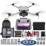
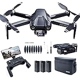
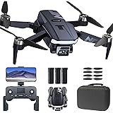
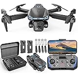
Essential Components for Your DIY Tricopter
Building a custom tricopter demands meticulous component selection, as each part plays a pivotal role in the vehicle’s performance, stability, and longevity. The synergy between these components dictates the ultimate flight characteristics and the overall success of the build. Here, we outline the primary constituents necessary for any aspiring tricopter builder.
-
Frame: The structural backbone of your tricopter, frames typically come in various materials such as carbon fiber, G10 fiberglass, or aluminum. Carbon fiber offers superior strength-to-weight ratio and rigidity, crucial for minimizing vibrations and maximizing flight performance. The frame’s design must accommodate the unique rear tilt mechanism and provide ample space for all electronic components.
-
Brushless Motors: Three motors are required, chosen based on KV rating (RPM per volt) and thrust capabilities relative to the expected all-up weight (AUW). For a typical tricopter, motors in the 900-1200KV range are common, paired with appropriately sized propellers (e.g., 8-10 inch). Ensuring all three motors are identical in specification is critical for balanced thrust.
-
Electronic Speed Controllers (ESCs): These devices translate the flight controller’s commands into motor speed. Three ESCs are needed, matching the motor’s current draw capabilities. Modern ESCs support various protocols like DShot, OneShot, and MultiShot, offering faster and more precise communication with the flight controller, which is particularly beneficial for PID tuning and responsive control.
-
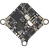
Flight Controller (FC): The “brain” of the drone, responsible for interpreting pilot inputs, stabilizing the aircraft, and managing motor outputs. Popular choices for DIY builds include boards running open-source firmware like Betaflight, ArduPilot, or INAV. The FC should have sufficient processing power, an integrated Inertial Measurement Unit (IMU – accelerometer and gyroscope), and ideally, a Barometer for altitude hold.
-
Power Distribution Board (PDB) / Integrated FC: A PDB simplifies wiring by distributing power from the battery to the ESCs and FC. Many modern flight controllers now integrate a PDB directly, or even ESCs, reducing clutter and simplifying the build. Consider one with current sensing and voltage regulation for auxiliary components.
-
Battery: High-discharge Lithium Polymer (LiPo) batteries are standard. Select a battery with appropriate voltage (e.g., 3S or 4S) and capacity (mAh) to achieve desired flight times and power delivery. The C-rating indicates the maximum safe continuous discharge rate, which should comfortably exceed the combined peak current draw of your motors.
-
Radio Transmitter and Receiver (Tx/Rx): A reliable radio link is paramount for control. Choose a system that operates on common frequencies (2.4GHz is standard) and offers features like telemetry, which provides real-time flight data back to the pilot. Popular protocols include Crossfire, ELRS, and FrSky ACCST/ACCESS.
-
Yaw Servo: As discussed, a high-quality, high-torque digital servo is crucial for the rear motor’s tilt mechanism. Speed and precision are key attributes for this component to ensure crisp yaw response.
-
Propellers: Balanced propellers, typically matched to motor KV and battery voltage, are essential for efficient thrust and minimal vibrations. Two clockwise (CW) and one counter-clockwise (CCW) propellers are generally used, depending on the motor rotation direction and frame setup.
-
Connectors and Wiring: High-quality silicone wire (appropriate gauge), XT60 or XT30 connectors, and various smaller connectors (JST, servo plugs) are necessary for reliable power and signal transmission throughout your custom tricopter build.
The Build Process: A Phased Approach to Constructing Your Custom Tricopter
The construction of a custom tricopter is a methodical process that demands patience and precision. Following a phased approach minimizes errors and ensures a robust and reliable flying platform. This sequence aligns with many of the visual cues presented in the video, providing critical context for each step.
Frame Assembly and Motor Mounting
Begin by assembling the frame according to the manufacturer’s instructions. This often involves attaching the arms to the main body plate and securing them firmly. Ensure all screws are tightened appropriately, perhaps with a drop of threadlocker on metal-to-metal connections to prevent loosening due to vibration. Subsequently, mount the brushless motors to the end of each arm. The rear arm will feature the unique tilting mechanism for the yaw servo, so ensure its pivot points are free-moving but without excessive play.
ESC Installation and Power Distribution
Next, install the ESCs. These can be mounted directly on the arms, near the motors, or centrally on the main frame. Wiring the ESCs to the PDB (or integrated FC) is a critical step. Solder the ESCs’ power leads to the corresponding positive and negative pads on the PDB, ensuring correct polarity. Then, connect the three signal wires from each ESC to the appropriate motor output pins on the flight controller. It is imperative to maintain clean soldering joints and proper insulation to prevent shorts.
Flight Controller Integration and Sensor Placement
Mount the flight controller centrally on the frame, ideally using vibration-damping standoffs. This minimizes the impact of frame vibrations on the FC’s sensitive gyroscopes and accelerometers. Connect the ESC signal wires, battery power (if not integrated), and any auxiliary components like the radio receiver, GPS module, or FPV equipment to their designated ports on the FC. Carefully route all wiring to avoid interference with moving parts or propellers.
Radio Receiver Pairing and Yaw Servo Linkage
Before connecting the servo, pair your radio receiver with your transmitter. Once bound, connect the receiver to the flight controller using the appropriate protocol (e.g., SBUS, CRSF, iBUS). Then, install the yaw servo into its mount on the rear arm. Connect the servo’s signal wire to the designated servo output pin on the flight controller, and ensure it receives proper power (often via the FC’s 5V rail). Mechanically link the servo horn to the rear motor mount, ensuring smooth, unobstructed movement of the motor tilt mechanism throughout its full range of motion. Precision in this linkage directly impacts yaw response and stability.
Firmware and Calibration: The Brains of the Operation
With the physical assembly complete, the electronic brain of your tricopter requires meticulous configuration. This phase involves flashing firmware, calibrating sensors, and fine-tuning the flight parameters to achieve stable and responsive flight. This is where your custom build truly comes to life.
Firmware Flashing and Initial Setup
Begin by flashing your chosen flight controller firmware (e.g., Betaflight, INAV, ArduPilot) onto the FC board. Connect the FC to your computer via USB and use the corresponding configurator software. Once flashed, perform an initial setup, including selecting the correct board orientation, motor layout (crucial for a tricopter!), and ESC protocol. Configure your radio receiver inputs to ensure the flight controller correctly interprets stick movements.
Accelerometer and Gyroscope Calibration
Calibrate the accelerometer and gyroscope sensors on the flight controller. Place the tricopter on a perfectly level surface and follow the software’s calibration procedure. This teaches the FC its ‘level’ reference point, which is fundamental for stable flight and accurate attitude hold. A miscalibrated IMU can lead to significant drift or instability immediately upon takeoff.
ESC Calibration
Calibrating the ESCs ensures they all respond uniformly to the flight controller’s throttle commands. This process typically involves powering the ESCs with full throttle from the FC, then dropping to zero throttle, allowing the ESCs to learn the full range. Some modern ESC protocols (like DShot) do not require manual calibration, but for others, it’s a vital step to prevent uneven motor thrust, which directly impacts stability. Uneven thrust from disparate ESC responses can make your custom tricopter unpredictable.
PID Tuning: The Art of Flight Dynamics
PID tuning is arguably the most critical and iterative aspect of flight controller configuration. The P (Proportional), I (Integral), and D (Derivative) gains determine how the flight controller reacts to errors in attitude and corrects them. For a tricopter, careful PID tuning is essential to achieve stable flight, precise control, and smooth yaw response, especially given the mechanical yaw mechanism. Start with conservative default values, then incrementally adjust P, I, and D gains through test flights, observing how the drone reacts to stick inputs and wind. Look for oscillations (too high P), drift (improper I), or sluggish response (too low D). Imagine if your vehicle consistently overshoots its target; tuning fixes this.
Pre-Flight Checks and Initial Hover
Before the maiden flight, a series of meticulous pre-flight checks are absolutely non-negotiable. These steps ensure the safety of the pilot, spectators, and the aircraft itself, mitigating risks associated with a new build. Always prioritize safety in drone operations.
First, double-check all wiring for correct polarity, secure connections, and proper insulation. Verify that all propellers are installed in the correct direction and orientation (CW/CCW), and that they are tightened appropriately. Improper propeller direction is a common error that prevents lift. Power on your radio transmitter and ensure it’s communicating with the receiver. Then, connect the main flight battery, listening for the ESC initialization tones. Observe the flight controller’s LED indicators for any error codes. Confirm that the drone arms successfully and that motor spin directions match the configurator’s diagram. If any motor spins incorrectly, rectify the wiring or ESC settings before proceeding. Finally, conduct a quick safety check of your chosen flight area, ensuring it’s clear of obstacles and people. Perform the initial hover in an open, calm environment, preferably outdoors, or in a large, well-ventilated indoor space. Expect minor drifts or wobbles and be prepared to disarm instantly.
Advanced Considerations for the Experienced Builder
For those who seek to push the capabilities of their custom tricopter beyond basic flight, several advanced integrations can enhance its functionality and utility. These additions elevate the drone from a simple flying platform to a sophisticated aerial tool.
-
Telemetry Integration: Adding telemetry allows real-time flight data (battery voltage, current draw, GPS coordinates, RSSI, flight mode) to be transmitted back to the pilot’s radio or ground station. This critical information aids in flight planning, monitoring system health, and preventing unexpected failures, such as battery depletion.
-
GPS Modules: Integrating a GPS module enables advanced flight modes such as Position Hold, Return To Home (RTH), and Waypoint Navigation. These features are invaluable for autonomous operations, long-range flights, or simply providing a safety net if control is temporarily lost. The precision of a GPS module heavily influences the accuracy of these autonomous functions.
-
First-Person View (FPV) Systems: Equipping your tricopter with an FPV camera and video transmitter allows for immersive aerial piloting. This involves a small camera, a video transmitter (VTX), and a pair of FPV goggles or a monitor. High-quality FPV systems provide low-latency video feed, crucial for precise control during agile flight or for capturing aerial videography.
-
Payload Capacity and Gimbal Integration: Depending on the frame’s strength and motor thrust, a tricopter can be designed to carry small payloads, such as action cameras or specialized sensors. Integrating a brushless gimbal can stabilize a camera, producing buttery-smooth aerial footage even during dynamic flight. This requires careful consideration of weight distribution and motor sizing.
-
Long-Range Capabilities: For extended flight ranges, consider upgrading to a long-range radio system (e.g., LoRa-based systems) and potentially a larger capacity battery. Antenna selection and placement become paramount to maintain a robust control link and video feed over significant distances. Furthermore, power efficiency and aerodynamic considerations play a larger role in optimizing flight duration.
Optimizing Tricopter Performance: From Setup to Sky
Achieving optimal performance from your custom tricopter involves a holistic approach that extends beyond basic assembly and initial calibration. This continuous refinement ensures the drone not only flies stably but also performs precisely as intended under various conditions. Consequently, attention to detail in these areas differentiates a good build from an exceptional one.
One critical area for optimization is vibration management. Excessive vibrations can negatively impact the flight controller’s IMU, leading to unstable flight and poor PID performance. Ensure motors are securely mounted, propellers are balanced, and the flight controller is adequately soft-mounted. Furthermore, the selection of the correct propeller pitch and diameter, matched to your motors’ KV rating and battery voltage, significantly influences thrust, efficiency, and flight characteristics. Experimentation within safe parameters can yield substantial improvements in flight time or agility.
Moreover, advanced PID tuning techniques, often involving blackbox logging analysis, can help identify and rectify subtle flight imperfections. This allows for a data-driven approach to fine-tuning, pushing the boundaries of flight stability and responsiveness. Imagine if you could pinpoint the exact frequency of an oscillation and directly address it with filter settings; blackbox logging makes this possible. The servo for the yaw mechanism also benefits from specific tuning, ensuring a crisp, backlash-free response that aligns with the pilot’s commands. Ultimately, the quest for optimal tricopter performance is an ongoing journey of learning and iterative refinement, rewarding the dedicated builder with a truly unique and capable aerial platform.
Tricopter Workshop Wisdom: Q&A
What is a tricopter?
A tricopter is a type of drone that is uniquely distinguished by having three motors for flight, unlike more common quadcopters which have four.
How does a tricopter steer or turn (yaw) differently from a quadcopter?
A tricopter uses a special servo-controlled mechanism on its rear motor to physically tilt the propeller, which provides very precise turning control. Quadcopters, on the other hand, change speed of their motors to turn.
What are some key parts I need to build a DIY tricopter?
You will need a frame for the structure, three brushless motors for thrust, Electronic Speed Controllers (ESCs) to manage motor speed, a Flight Controller as the “brain,” and a battery for power.
What is the “Flight Controller” in a tricopter?
The Flight Controller is like the “brain” of the drone; it takes your commands, helps stabilize the aircraft, and tells the motors what to do so it can fly correctly.