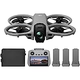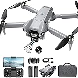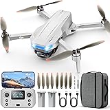
The agricultural sector continuously evolves. Precision agriculture stands at the forefront. Unmanned Aerial Vehicles (UAVs) are integral to this shift. Specifically, hexacopter agricultural drones offer significant advantages. They enhance crop monitoring and plant protection. These sophisticated tools deliver targeted spraying. This reduces chemical waste and improves efficiency. Understanding their assembly is crucial. The video above provides an essential visual guide. It covers the intricate process of building an advanced agricultural drone. This article expands on those vital steps. It offers deeper insights for expert users.
Assembling a high-performance hexacopter demands precision. Every component plays a critical role. From motor wiring to flight controller calibration, accuracy is key. This detailed guide ensures proper functionality. It also guarantees operational safety. The process is complex. However, a systematic approach simplifies it. This article focuses on expert-level instructions. It uses industry-standard terminology. It supports the successful deployment of your agricultural drone.
Essential Components for Agricultural Drone Assembly
Building a robust plant protection drone starts with components. Each part is selected for performance. The drone frame provides the structural foundation. A spray system ensures precise application. High-efficiency motor sets provide propulsion. The control system manages flight dynamics. A reliable power system supplies energy. Specialized tools facilitate assembly. Quality components are paramount. They ensure long-term reliability. Substandard parts compromise operational integrity. Invest in proven technology for optimal results.
Pre-Assembly: Accessory Welding and Wiring
Welding and wiring demand meticulous attention. Before frame assembly, several connections are made. Motors require careful soldering. The CANHUB module is integrated. PMU and water pump connections are secured. Camera wiring also needs precision. Motor cable preparation is an example. Cables are inserted into plastic pipes. Heat shrink tubing secures the ends. A heat gun fixes the tubing. Plug sheaths are then added. The plug is fixed using a welding fixture. Female headers are soldered to the cables. Polarity must be strictly observed. Positive and negative connections are crucial. Remaining plugs are processed identically.
- Motor cables are routed through protective piping.
- Heat shrink tubing ensures insulation integrity.
- Precise soldering of connectors is non-negotiable.
- Positive and negative terminals must be correctly aligned.
Hexacopter Frame Installation and Structure
The drone frame forms the backbone. Its proper assembly ensures structural integrity. Start by unpacking all components. The cover and control board are removed first. Turn the drone body over. Access the distribution board cover. This exposes internal connection points. The AS150U cable and holder are installed. Secure this component to the drone body. Pay strict attention to polarity. This prevents critical electrical faults. Always verify connections before proceeding.
Integrating Power Holders and Frame Legs
Power holders are essential for battery placement. They also support the frame legs. Install the power holder onto the frame leg. Insert this assembly into the mounting seat. This is located at the rear of the drone body. Tighten the leg and all associated screws. Repeat this for the remaining frame legs. Ensure the side with the screw faces outward. Insert the leg support rails. Tighten these screws securely. This step provides critical stability. It prepares the hexacopter for payload and flight dynamics.
Arm and Motor Integration for Propulsion
The arms house the propulsion system. Proper installation is critical. Sleeve the arm tube into the folding part. Secure it firmly with screws. Attach the arm tube clamp at the folding joint. Insert the arm locking cap. Next, install the X8 motor set. Pass the motor cables through the arm tube. Route them into the drone body. Fix each motor securely. This prevents dislodgement during flight. Motor orientation is key for thrust vectoring.
Strategic Motor Placement and Wiring
Motor placement follows a specific sequence. The camera defines the drone’s nose. Motors are numbered M1 to M6, left to right. CW (clockwise) motors are installed at M2, M4, and M6. CCW (counter-clockwise) motors are placed at M1, M3, and M5. This alternating pattern creates stable lift. Install each arm with the screw side facing up. Remove the locking cap. Insert the arm, aligning all holes. Ensure it reaches the hole limitation. Fix the plugs. Tighten locking caps and screws. Complete this for all arms. Then, turn the drone body over. Secure any remaining screws. Install water pipe clamps on M1, M2, M3, and M6 arms. These clamps secure the spraying system lines.
- M1, M3, M5: Counter-Clockwise (CCW) motors.
- M2, M4, M6: Clockwise (CW) motors.
- Correct motor rotation ensures stable lift.
Tank and Spraying System Installation
The tank holds the liquid payload. Its secure installation is vital. Assemble all tank accessories. Insert the filter and tank cover. These go into the bottom outlet. Mount the tank onto the frame legs. Verify the tank aligns with the drone body direction. This maintains balance. Install water pipe clamps on the two front legs. These guide the spray lines.
Precision Spraying System Setup
The spraying system ensures targeted application. Install the water pump centrally. Position it at the bottom of the tank. Soften the water pipe with a heat gun. Connect it to the water pump’s inlet. The other end connects to an L-shaped double-pass. Cut the pipe to a suitable length. Connect the tank’s bottom outlet to the flow meter inlet. This uses another water pipe. Arrange the waterway layout. The water pump outlet connects via L-type and T-type interfaces. Secure these connections within the water pipe clamps. Position them on the frame legs. Optionally, the pump can be installed at the rear of the tank. The waterway layout remains similar. After routing, pass the pump’s cable through the drone body. Insert it into the distribution board. Install nozzle parts. Place them beneath M1, M2, M3, and M6 arm motors. Fix them with screws. Connect four extended nozzles and pneumatic heads. Use water pipes and T-type interfaces. This completes the distribution network. The flow meter signal wire integrates into the flight control system.
Advanced Radar System Integration
Radar systems provide critical situational awareness. They enhance flight safety. Assemble the ground radars first. Then, assemble front and rear obstacle avoidance radars. These units are crucial for autonomous operations. They prevent collisions and maintain terrain following. Accuracy in installation is paramount for effective performance.
Strategic Radar Placement and Connectivity
Install the ground radar above the pump. The rear obstacle avoidance radar mounts below the pump. The front obstacle avoidance radar goes in front of the tank. This provides comprehensive 360-degree detection. These placements optimize sensor coverage. Radar signal cables are routed. They pass through the drone body. They connect to the CANBUS module. This integration allows the flight controller to process radar data. Precise positioning avoids interference. It ensures reliable detection capabilities.
Flight Control System Installation and Wiring
The flight control system is the drone’s brain. Accurate installation is paramount. Use 3M glue to fix the main controller. Position it in the board’s middle. The arrow must face the drone’s head. Insert M1 to M6 motor signal wires. Connect them to their corresponding main controller ports. This establishes motor command pathways. Incorrect wiring compromises flight stability. Double-check all connections. This prevents system malfunctions during operation.
Critical Component Connections
Fix the PMU (Power Management Unit). Insert its plug into the power distribution board. Connect its signal wire into the POW port. This supplies stable power to the flight controller. Fix the receiver and CANHUB module. Insert the receiver plug into the distribution board. Connect its other end to the flight control CAN1 port. The CANHUB facilitates communication between various peripherals. Insert the LED cable into the main control board. Use 3M glue to fix the LED light. Position it at the tail light cover. This provides visual status indicators. Install GPS on the M1 arm. Insert the GPS cable into the main control. GPS provides crucial positioning data. Install the camera at the drone’s head. Insert its power cable into the distribution board. Connect its signal wire to the data transmission port. Insert the flowmeter signal wire into the XT port. The T12 receiver’s 6P cable goes into the data transmission port. Its S-Bus wire connects to the main control RC port. Another data wire inserts into the LINK port. This ensures comprehensive data telemetry.
RTK System for Enhanced Precision
RTK (Real-Time Kinematic) technology enhances GPS accuracy. Fix the RTK module. Insert its 5P plug into the RTK FC port. Insert the 2P plug into the main control EXT1. Connect the power cable to the CANHUB 12V port. Insert the radar signal cable into the CANBUS module. Route it through the frame body. Install RTK components on the M3 and M6 arms. Insert antenna wires through the arms. Connect them to the RTK receiver. The M3 wire goes to the PRI port. The M6 wire connects to the SEC port. Install antenna protection covers. Finally, fix the flight control board and the main cover. This completes the hardware installation. The integrated RTK system achieves centimeter-level positioning accuracy. This is vital for precision agriculture tasks.
Rigorous Flight Debugging and Calibration
Post-assembly debugging ensures optimal performance. Level the assembled drone precisely. Use a level tool to adjust motors. Tighten all screws securely. All six motors require leveling. This prevents flight instability. Test the drone outdoors. Use a multimeter for short-circuit detection. No beeping indicates normal power plug function. Remove the battery board. Secure the battery with a bandage. Place it back on the tank. Measure the battery voltage. A reading of 50.5V, for example, is noted. This value is used for remote control voltage calibration.
Remote Control and APP Configuration
Turn on the remote control. Power on the drone. Open the H12 tool. Access advanced options. Enter the password (e.g., 8888). Click “adjust parameters.” Channels 1-5 typically require no debugging. Channels 6-9 are customizable. Set CH6 as ‘F’, CH7 as ‘A’, CH8 as ‘B’, and CH9 as ‘H’. Save these settings. Open the Agri Assistant APP. Log in or register an account. Connect to the H12 controller. Click “start.” Access the menu. Select “RC calibration.” Calibrate all joystick levers (up, down, left, right). Confirm normal joystick operation. Click “gate set.” Customize channels further. Set CH6 as “back,” CH7 as “pump,” CH8 as “engine,” CH9 as “AB.” Save these settings. Set RC mode to “model 1” and save. This configures the operational controls.
Sensor Calibration and System Settings
Navigate to the sensor page (second icon). Click “compass calibration.” Rotate the drone horizontally. The LED light turns green. Erect the drone. Continue rotating until the LED flashes. Put it down. Power off and then on again. This completes compass calibration. Set battery parameters. Select “hang” for low voltage protection. Set the first level to 50.4V. Set the second level to 49V. Input the measured voltage (e.g., 50.5V) into “measure VOL.” Configure spray settings. Set leak protection to “HANG.” Set work mode as “single pump.” Save these settings. Most other parameters usually do not need adjustment. Access advanced settings (fourth icon). Enter 8888. Click “install position.” If the flight controller is centered, no adjustment is needed. Otherwise, measure arm distances. Input numbers for X, Y, Z axes. X is the vertical axis of the machine head. Y is the horizontal axis. Z is the vertical direction. Click “flight gate.” Set the second gear to “manual.” Set the third gear to “AB work.” Save these settings. Test lever functionality. Select the correct drone frame type. For the E616P, select the six-axis type. Save the selection. Adjust sensitivity settings. Click “base sensitivity,” read, and save. Finally, configure map type. Select “Autonovi maps” for China. Choose “Google maps” for other regions. Set remote control type to H12. These meticulous steps ensure precise flight control and operational safety.
Final Spray and Flight Testing
Operational validation is the final stage. Power off the drone. Unfold all arms. Power on again. Pour some water into the tank. Initiate spray testing. Empty any air from the nozzles. Tighten them firmly. Verify normal spray patterns. This confirms the spraying system functionality. Next, prepare for flight. Power off the drone. Install the paddles on each motor. Tighten screws securely. Ensure CCW and CW paddles match their respective motors. Incorrect paddle installation leads to catastrophic failure. Power on the hexacopter agricultural drone. Perform unlocking procedures. Dial both levers 45 degrees down to the center. Turn on power. Use the right joystick to test motor response. Left lever stops left motors. Right lever stops right motors. Forward movement stops front motors. Backward movement stops rear motors. Turn the left joystick up. The drone will take off. Test forward, backward, left, and right movements. Verify flight performance. Press the ‘A’ button to activate spraying. Observe normal drone operation. Lower the left joystick to land. The hexacopter agricultural drone is now fully debugged. It is ready for field deployment. This comprehensive process ensures reliable, efficient performance for precision agriculture tasks.
Agricultural Hexacopter Installation: Your Q&A
What is a hexacopter agricultural drone?
A hexacopter agricultural drone is an Unmanned Aerial Vehicle (UAV) with six propellers designed for farming tasks. It helps with things like crop monitoring and plant protection in modern agriculture.
Why are hexacopter agricultural drones useful in farming?
They deliver targeted spraying, which reduces chemical waste and improves efficiency in farming. These drones also enhance crop monitoring and plant protection efforts.
What are some key parts needed to build an agricultural drone?
Essential components include the drone frame, a spray system, high-efficiency motor sets for propulsion, a control system for flight, and a reliable power system.
What is the purpose of the spray system on an agricultural drone?
The spray system is designed to ensure precise application of liquids, like fertilizers or pesticides, onto crops. This helps farmers apply treatments exactly where they are needed.